- 您现在的位置:买卖IC网 > Sheet目录335 > ISL97691IRTZ-TK (Intersil)IC LED DRVR BACKLIGHT 3D 16TQFN
�� �
�
�ISL97691�
�1.35� � 24.53� � (� 4� � 0.03� )�
�I� L� =� -----------------------------------------------------------------� =� 1.47A�
�(� 8.65� � 10�
�)�
�f� SW� =� --------------------------------�
�Boost� Output� Voltage� Range�
�The� working� range� of� the� boost� output� voltage,� V� OUT� is� from� 40%�
�to� 100%� of� the� maximum� output� voltage,� V� OVP� ,� set� by� resistors�
�R� 1� and� R� 2� as� described� in� the� previous� section.�
�The� target� applications� should� be� considered� carefully� to� ensure� that�
�V� OVP� is� not� set� unnecessarily� high.� For� example,� using� R� 1� =� 470k� ?�
�and� R� 2� =� 23.7k� ?� per� the� Typical� Application� Circuit� on� page� 2� sets�
�V� OVP� to� between� 24.53V� to� 25.88V� when� tolerancing� is� considered.�
�The� minimum� voltage,� V� OVP� (min)� =� 24.53V,� sets� the� maximum�
�number� of� LEDs� per� channel� because� this� the� worst� case�
�minimum� voltage� that� the� boost� converter� is� guaranteed� to� supply.�
�The� maximum� voltage,� V� OVP� (max)� =� 25.88V,� sets� the� minimum�
�number� of� LEDs� per� channel� because� it� sets� the� lowest� voltage�
�that� the� boost� converter� is� guaranteed� to� reach:� 40%� x�
�25.88V� =� 10.35V.�
�Using� LEDs� with� a� V� F� tolerance� of� 3V� to� 4V,� this� V� OVP� example� is�
�suitable� for� strings� of� 4� to� 6� LEDs.� If� fewer� than� 4� LEDs� per�
�channel� are� specified,� V� OVP� must� be� reduced.�
�Switching� Frequency�
�The� boost� switching� frequency� is� adjusted� by� resistor� R� FSW�
�(Equation� 11):�
�10�
�(EQ.� 11)�
�R� FSW�
�Where:�
�f� SW� is� the� desirable� boost� switching� frequency� (Hz)�
�R� FSW� is� resistor� from� FSW� pin� to� GND� (� ?� )�
�Inductor�
�Choose� the� inductance� according� to� Table� 1:�
�TABLE� 1.� INDUCTOR� SELECTION�
�For� example,� for� a� system� using� 4� LED� channels� with� 30mA� per�
�channel� and� a� maximum� output� voltage� (OVP)� of� 24.53V� with� an�
�input� supply� of� 2.7V� minimum:�
�(EQ.� 13)�
�2.7�
�Output� Capacitor�
�It� is� recommended� that� a� 2.2μF� to� 3.3μF� X5R/X7R� or� equivalent�
�ceramic� output� capacitor� is� used.�
�Schottky� Diode�
�The� Schottky� diode� should� be� rated� for� at� least� the� same� forward�
�current� as� the� inductor,� and� for� reverse� voltage� to� at� least� the�
�maximum� output� voltage,� OVP.�
�Compensation�
�The� ISL97691’s� boost� regulator� uses� a� current� mode� control�
�architecture� with� a� standardised� external� compensation� network�
�connected� to� the� COMP� pin.� The� component� values� shown� in� the�
�Typical� Application� Circuit,� Figure� 1,� on� page� 1� should� be� used.�
�The� network� comprises� a� series� RC� of� 12k� ?� and� 15nF� also� from�
�COMP� to� GND.�
�Applications�
�Unused� LED� Channels�
�Connect� unused� LED� channels� to� GND.�
�High� Current� Applications�
�Each� channel� of� the� ISL97691� supports� 40mA� continuous� sink�
�current.� For� applications� that� need� higher� current,� multiple�
�channels� can� be� paralleled� (Table� 2).�
�TABLE� 2.� PARALLELING� CHANNELS� FOR� HIGHER� CURRENT�
�BOOST� FREQUENCY�
�400kHz� to� 700kHz�
�700kHz� to� 1MHz�
�1MHz� to� 1.5MHz�
�INDUCTANCE�
�10μH� to� 15μH�
�6.8μH� to� 10μH�
�4.7μH� to� 8.2μH�
�TOTAL�
�CHANNELS�
�4�
�2�
�1�
�CHANNEL�
�CURRENT�
�40mA� per� channel�
�80mA� per� channel�
�160mA�
�CHANNEL� CONNECTIONS�
�CH1,� CH2,� CH3,� CH4�
�{CH1� &� CH2},� {CH3� &� CH4}�
�{CH1� &� CH2� &� CH3� &� CH4}�
�1.5MHz�
�3.3μH� to� 4.7μH�
�NOTE:� PWMI_1� and� PWMI_2� must� driven� together� for� total� channels� 1.�
�The� inductor� saturation� current� rating� should� be� at� least� the�
�figure� provided� by� Equation� 12:�
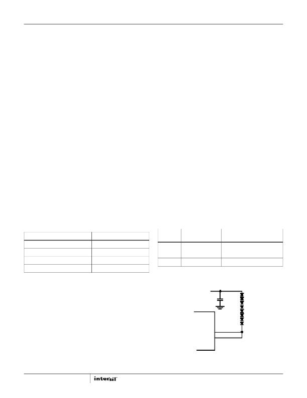
�The� example� below� shows� CH1� &� CH2� paralleled.�
�I� L� =� -----------------------------------------------------�
�1.35� � V� OUT� � I� LED�
�V� IN�
�Where:�
�(EQ.� 12)�
�I� L� is� the� minimum� inductor� saturation� current� rating� (A)�
�V� OUT� is� the� maximum� output� voltage� set� by� OVP� (V)�
�I� LED� is� the� sum� of� the� channel� currents� (A)�
�VIN� is� the� minimum� input� voltage� (V)�
�If� the� calculation� produces� a� current� rating� higher� than� the� 3.15A�
�maximum� boost� switch� current� limit,� then� a� 3A� inductor� current�
�rating� is� adequate.�
�14�
�CH1�
�CH2�
�FIGURE� 22.�
�FN7840.1�
�February� 1,� 2013�
�发布紧急采购,3分钟左右您将得到回复。
相关PDF资料
ISL97693IRTZ-TK
IC LED DRVR BACKLIGHT 16TQFN
ISL97901CRZ
IC LED DRVR 1.5A 28QFN
ISO1I811T
ISOLAT DGTL 500VAC 8CH 48TSSOP
ISO7221AQDRQ1
IC DGTL ISOLATOR 1MBPS DL 8SOIC
ISOBAR4 ULTRA
SURGE SUPPRSSR 4OUT 6'CORD W/LED
ISOBAR6 ULTRA
SURGE SUPPRSSR 6OUT 6'CORD W/LED
ISOBAR6DBS
SURGE SUPP DSS 6OUT 6'CORD W/LED
ISOBAR6ULTRAHG
SURGE SUPP 6OUT 15'CORD HOSP GRD
相关代理商/技术参数
ISL97692IIZ-T
制造商:Intersil Corporation 功能描述:4 CH W/12-BIT PWM DIMMING SINGLE CELL LI-ION BATTERY POWERED - Tape and Reel
ISL97692IRTZ
制造商:Intersil Corporation 功能描述:4 CH W/12-BIT PWM DIMMING SINGLE CELL LI-ION BATTERY POWERED - Rail/Tube 制造商:Intersil Corporation 功能描述:IC LED DRVR BACKLIGHT 16TQFN 制造商:Intersil 功能描述:4CH w/12Bit PWM Dim Li-ION LED Driver
ISL97692IRTZ-T
制造商:Intersil Corporation 功能描述:4 CH W/12-BIT PWM DIMMING SINGLE CELL LI-ION BATTERY POWERED - Tape and Reel 制造商:Intersil 功能描述:4CH w/12Bit Dimming Li-Ion LED Driver
ISL97692IRTZ-TK
制造商:Intersil Corporation 功能描述:4 CH W/12-BIT PWM DIMMING SINGLE CELL LI-ION BATTERY POWERED - Tape and Reel 制造商:Intersil Corporation 功能描述:IC LED DRVR BACKLIGHT 16TQFN 制造商:Intersil 功能描述:4CH w/12Bit Dimming Li-Ion LED Driver
ISL97693IRTZ
功能描述:IC LED DRVR BACKLIGHT 16TQFN RoHS:是 类别:集成电路 (IC) >> PMIC - LED 驱动器 系列:- 产品培训模块:Lead (SnPb) Finish for COTS
Obsolescence Mitigation Program 标准包装:2,500 系列:- 恒定电流:- 恒定电压:- 拓扑:升压(升压),切换式电容器(充电泵) 输出数:1 内部驱动器:是 类型 - 主要:背光 类型 - 次要:白色 LED 频率:625kHz ~ 875kHz 电源电压:2.7 V ~ 5.3 V 输出电压:5V 安装类型:表面贴装 封装/外壳:10-TFSOP,10-MSOP(0.118",3.00mm 宽) 供应商设备封装:10-µMAX 包装:带卷 (TR) 工作温度:-40°C ~ 85°C
ISL97693IRTZ-T
功能描述:IC LED DRVR BACKLIGHT 16TQFN RoHS:是 类别:集成电路 (IC) >> PMIC - LED 驱动器 系列:- 产品培训模块:Lead (SnPb) Finish for COTS
Obsolescence Mitigation Program 标准包装:2,500 系列:- 恒定电流:- 恒定电压:- 拓扑:升压(升压),切换式电容器(充电泵) 输出数:1 内部驱动器:是 类型 - 主要:背光 类型 - 次要:白色 LED 频率:625kHz ~ 875kHz 电源电压:2.7 V ~ 5.3 V 输出电压:5V 安装类型:表面贴装 封装/外壳:10-TFSOP,10-MSOP(0.118",3.00mm 宽) 供应商设备封装:10-µMAX 包装:带卷 (TR) 工作温度:-40°C ~ 85°C
ISL97693IRTZ-TK
功能描述:IC LED DRVR BACKLIGHT 16TQFN RoHS:是 类别:集成电路 (IC) >> PMIC - LED 驱动器 系列:- 产品培训模块:Lead (SnPb) Finish for COTS
Obsolescence Mitigation Program 标准包装:2,500 系列:- 恒定电流:- 恒定电压:- 拓扑:升压(升压),切换式电容器(充电泵) 输出数:1 内部驱动器:是 类型 - 主要:背光 类型 - 次要:白色 LED 频率:625kHz ~ 875kHz 电源电压:2.7 V ~ 5.3 V 输出电压:5V 安装类型:表面贴装 封装/外壳:10-TFSOP,10-MSOP(0.118",3.00mm 宽) 供应商设备封装:10-µMAX 包装:带卷 (TR) 工作温度:-40°C ~ 85°C
ISL97694AIRTZ
制造商:Intersil Corporation 功能描述:6 CH W/12-BIT PWM DIMMING SINGLE CELL LI-ION BATTERY POWERED - Rail/Tube 制造商:Intersil Corporation 功能描述:IC LED DRVR BACKLIGHT 20TQFN